Version 2.1 of Domus.Cad Pro and Std, a complete BIM, parametric architectural 3D CAD, was released.
Major novelties include:
- New “smart” inspector
- OpenBim IFC 2×3 support
- DXF, DWG, DWF and SVG import/export improvements
- New RoofTiles module for creating 3D roof tiles
- New Super2Dto3D module for easy and fast converting a 2D drawing to 3D model
- New Map2Cad module for getting maps from Google Maps
- SuperPipe and SupeRot improvements
- Optimization for new operating system
- New documentation with several movies
- ..and many more
See details below.
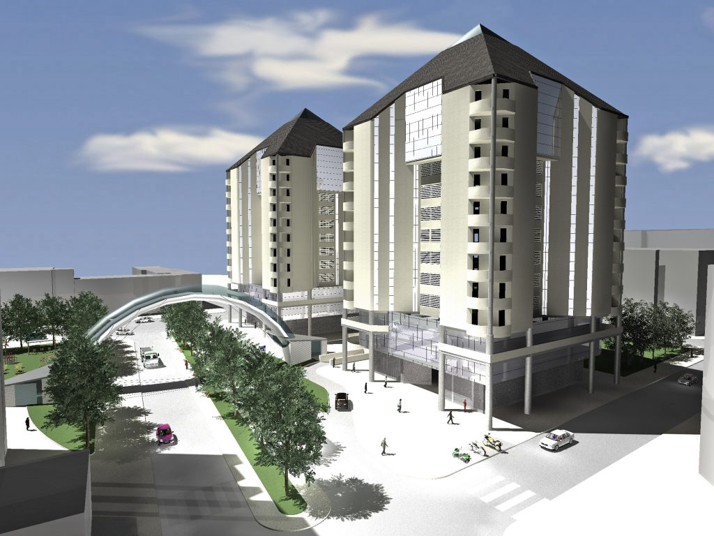
Table of contents
Dimensioning the Inspector Window
Customize the standard position of the windows
Setting up the standard window positions
Interactive messages tracing/modification
Extension Import/Export of files in various formats
Possibility to export/import files in DWF format added
Export format added Scalable vector Graphics (SVG)
Exports in IFC 2×3 format (Industry Foundation Classes)
Map2Cad
Optimization of the zoom function on 3D views
Optimization for newer operating systems
Interactive messages drawing/modification
Selection rectangle with intersection of elements
New instruction manuals and new videos
The inspector palette
An important new feature of Domus.Cad Pro 2.1 is the introduction of the Inspector window.
This new window integrates and replaces the following windows: Information, Coordinates, Attributes, Insert Measurements and Edit Elements.
It is always in the foreground, allowing you to quickly carry out the operations most frequently performed when drawing.
The main characteristics of Inspector are:
- It’s contextual. Palette contents change according to current operation
- Single function for inserting and modifying
- Always in the foreground, no need to expressly bring it up
- Modifications are visible directly on drawing, in real-time
- Allows you to switch from the mouse to numeral for insertion/modification and vice versa at any time
- Has two layouts, horizontal and vertical
- Adds new operating modes
- Adapts to high-resolution monitors
The Inspector window is dynamic and changes according to the current operation.
So even new users can see instantly which operations are possible for each element.
The window can be horizontal:
or vertical:
according to requirements and position of other windows. It can be placed anywhere on the screen.
To modify, just click on bottom right-hand corner and drag until the selection rectangle is vertical or horizontal, as required.
Let’s take a closer look at the various operations.
Introduction of new elements
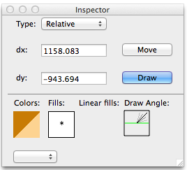
You can insert new elements entering measurements with the keyboard. You can choose from three possible modes in the Type menu: Relative, Absolute or Polar.
– Relative allows you to introduce dx/dy values in relation to the last point which was clicked on, introduced or modified, which can be visualized by pressing “w” or clicking on the icon on the toolbar:
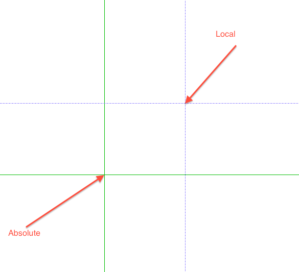
-Absolute allows you to introduce the X,Y values by using absolute coordinates. These are relative to the origin of the axes. Visualization of the origin of the absolute coordinates can be enabled or disabled using the button on the toolbar:
If local origin of the coordinates is enabled
the reference for coordinates is the origin of the relative coordinates. The coordinates appear in red to highlight the fact that their reference is no longer absolute zero and the menu name changes from “Absolute” to “Local”.
In plan view the axes of absolute coordinates are green, while those of local coordinates are blue.
-Polar allows you to introduce values of angle and distance. The reference is always to the last point which is clicked, introduced or modified, as for the introduction of relative coordinates.
In plan view, two green spots indicate the point of departure, while the point of arrival is marked by red spots. To insert the element in the desired position, simply press “Enter” on the keyboard or click on the “Draw” button with the mouse.
You can also just move the reference point to a new position by clicking the “Move” button.
When inserting new elements, you can choose their fill, material, thickness etc. In more detail:
Walls
You can choose the material:
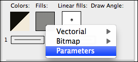
fills using the menu:
Vectorial:
Bitmap:
or access fills parameters directly:
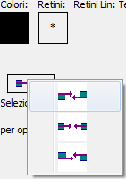
mode of insertion (centre, inner border, outer border):
Mac os X Win
angle for insertion:
The angle of insertion will be indicated by the relative icon:
Please note that the thickness of walls is a global setting, i.e., it applies to all walls and the setting can be changed in Wall parameters.
Segments – very similar to walls. In place of fills you can choose linear fills. You can also choose thickness and type of hatching:
Texts and Dimensions – choice of material.
In dimensions you can insert dimension points – press “Confirm” to confirm. To do so, of course, you must have inserted at least 2 dimension points.
Polygons – you can choose Material, Fill, Linear Fill, Thickness and Hatching.
Slabs – you can choose Material and Fill.
For polygons and slabs, you can insert the various vertices and generate the element by pressing “Return” on the keyboard or clicking the “Confirm” button in the window.
The “Confirm” button becomes visible for polygons when the third vertex is added, for slabs when the second vertex is added.
Stairs – you can choose Material and Fill.
Doors and Windows – you can choose Material, Fill and type.
The listed elements visualized on the menu correspond to windows (doors) with straight reveals, inclined reveals, straight niche, inclined niche or no reveals.
All of the information and indications previously found in the “Information” palette are now in Inspector:
You can still access the old Information, Coordinates and Attributes palettes through the Options->Windows menu.
Editing elements
If an element is selected, the window allows you to carry out various operations, depending on which element is involved. To confirm the change, press the “Return” key or click on the “Confirm” button.
You can work using relative, absolute, local or polar coordinates, exactly as for inserting new elements.
Information on the selected element is visualized near the bottom of the Inspector window, or on the right if the window is horizontal.
You can change material, fill, thickness, hatching etc. by clicking on the appropriate button to choose the new attribute.
Walls and Segments: The axis is always the reference for walls.
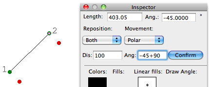
You can modify the length, angle, move the element and choose which point to reposition – end 1, end 2 or both. In the latter case the reference is the baricenter of the element. In plan view the old points are shown in green, the new ones in red.
To facilitate the operation, ends 1 and 2 are indicated on the plan.
An example:
Suppose we want to change the angle of a wall.
We select the wall and write the angle value in the specific field. We also choose which end to reposition – in this case, “End 2”.
We press Confirm and the wall moves to the desired position.
Another example:
Suppose we want to move a segment parallel to itself by a predetermined measurement.
One way might be to use the parallel transfer, but this involves a lot of steps. Inspector makes everything faster and easier.
We select the segment. We choose to reposition both ends and use the polar coordinates. We add +90° to the angle and insert the desired value of the move in the distance field, in this case 100 cm.
Then press Return, on the keyboard or click the Confirm button, to make the desired move.
Remember that all Domus.Cad fields are algebraic, so you can use expressions with brackets instead of numeric values.
So:
Equals:
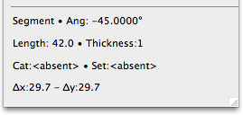
Information visualized for segments: angle, length, thickness, category, set, Delta X and Delta Y
Information visualized for walls: angle, length, thickness, height, category, set, Delta X and Delta Y, Area.
Polygons (Generic):
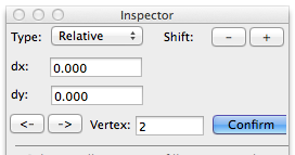
Any vertex can be edited and its value changed. Press the arrow keys to choose between the previous or next vertex. To make the changes permanent press “Return” on the keyboard or click on the Confirm button.
The “-” and “+” buttons allow you to move the vertex around. They are useful when we need to change the “open” side of a polygon. Plan view always shows the relevant vertex in green and its proposed modification in red.
The index of the first vertex and that of the previous and next vertices is also visualized.
Information visualized for generic polygons: total number of vertices in the polygon, thickness, area, category, set, Delta X and Delta Y.
Rectangle:
When a rectangle is selected two new editable fields appear in the window: Width and Height.
So we can change the measurement of width and height. The proportions of the two sides can be maintained by clicking on the special check-box.
So if one of the values is modified, the other is automatically calculated in real-time. The rectangle with its new measurements appears in red. As usual, press “Confirm” to make the changes permanent.
Circle:
As for the rectangle, you can change the radius or both radii along directions X and Y. Here, too, the circle is shown in red.
Arc:
You can change the numeric value of the radius for the arc too. The centre remains unchanged.
Roof slab:
Roof slabs are edited similarly to generic polygons. In addition, you can change the reference height of each single vertex.
In this case it is useful to be able to move through the vertices, because the reference of the roof pitch is given by side 1-2. In this way you can regenerate the roof facing a different direction.
Moving through the numbers of vertices also has a bearing on textures, which are always located parallel to side 1-2.
Doors and Windows:
Here you can change the length and type.
For other measurements and positions relating to the wall where they are located, check the Parameters window.
Information given is: for a door or window – width, height, measurement of window-sill (for windows) or threshold (for doors), category, set, Delta X, Delta Y and area.
Text:
Text can be moved and its angle varied as desired. The length field is disenabled because this measurement is calculated automatically depending on the number of characters.
Stairs:
Stairs can be moved and the length (corresponding to the width of the stair) and angle of steps can be modified.
Information visualized is: tread, reference height, height, category, set and number of treads. These values can be changed in the relative Parameters window.
Objects:
A selected object can be scaled, in which case the value inserted in “Scale” will be used to deform the object along the X, Y and Z axes (the latter, in the case of an object with 3D elements).
The angle can also be modified.
You can always choose which sides are to be repositioned,
so you have total spatial control over the object numerically. If you select “All”, the reference will be to the baricenter.
Another possibility is to use the precise measurements of the object. By inserting the Delta X and Delta Y values we obtain the exact size of the object in question. These changes leave the Z measurement as it is.
This function allows you, for example, to quickly move furnishing elements around a plan with the correct measurements.
Information for selected objects is: size, height, reference height, category, set and angle.
Dimensioning the Inspector Window
The Inspector window can now be re-dimensioned in various ways:
Reduced to an icon:
Mac os X Windows
Click on ![]() (Windows) or
(Windows) or ![]() (Mac OS X) to reduce it to an icon or, if reduced, to open Inspector.
(Mac OS X) to reduce it to an icon or, if reduced, to open Inspector.
Reduced to the dimensions of a panel
To do this click on the bottom right-hand corner and drag the corner of the window until it is approximately the size of a single panel.
In this case there is no difference between the horizontal and vertical positions.
Reduced to the dimensions of two panels
Horizontal:

Vertical:
To do this, modify the rectangular window until it is approximately the size of two panels – horizontal or vertical, as desired.
Dimension of three panels (default).
Horizontal:
In this position all panels are visible. It can be horizontal or vertical. To do this, simply modify the window until it is approximately the size of three panels – horizontal or vertical.
Standard position
The new Inspector window has made it possible to redesign the default layout of the various windows. Their position now changes depending on the resolution of the monitor. Visualization issues for low-resolution monitors with fewer pixels are very different from those of monitors with a high number of pixels. It is still possible, however, to put the window in your favorite position and save this work environment, so that your preferred configuration appears on startup.
 Standard position 2D-3D- vectorial with high-resolution monitor
 Standard position 2D-3D with high-resolution monitor
Standard position 2D with high-resolution monitor
 Standard position 2D-3D- vectorial with low-resolution monitor
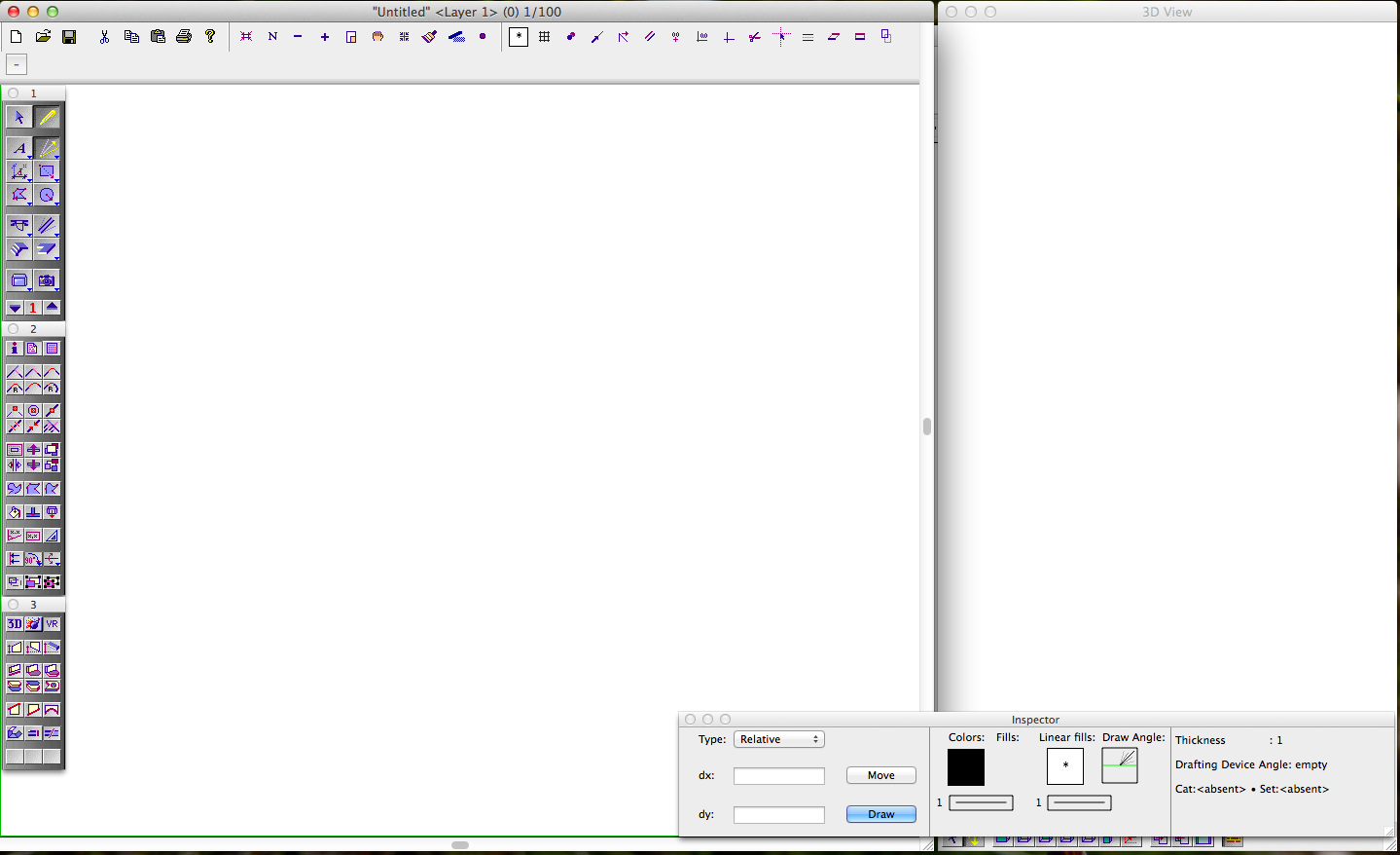
Standard position 2D-3D with low-resolution monitor
 Standard position 2D with low-resolution monitor
Customize the standard position of the windows
This new function enables you to customize the standard positions of the windows.
When you click on the “Save Operative Environment” function, the standard positions are memorized. If the 3D and vector rendering windows are open, then the 2D-3D- vectorial standard position is modified. If the 3D window is open but not that of vector rendering, then the 2D-3D standard position is modified. Lastly, if both windows are closed, the 2D standard position is modified.
The file also registers the resolution of the monitor where the document has been saved. So if the file is reopened on a computer with different resolution, one of the standard positions is automatically brought up, depending on which windows are open in the document.
Setting up the standard window positions
Now when the “Save Work Environment” function is brought up from the Options menu, the standard positions of the windows are saved on the disk. If both the 3D and vector rendering windows are open, this can be retrieved from Options->Windows >Standard Position 2D-3D- vectorial. If the 3D window is open but not the vector rendering one, then it can be retrieved from Options->Windows ->Standard Position 2D-3D. Lastly, if the 3D and vector rendering windows are closed, the association will be with the Standard Position 2D.
Restore program settings
By clicking on “Initial Preferences” in the Domus.Cad Preference Windows you can restore the initial settings:
Click on the various “Restore” buttons to cancel settings filed on the disk. “Preferences” refers to all of the parameters set using the “Save Operating Environment” function, while “Plug-in preferences” means the parameters of all modules.
“Standard windows position” are the positions of windows associated with standard positions.
The “Activated modules” option refers to the list of modules that can be used.
After using one of these functions it is advisable to exit the program and re-enter, so Domus.Cad can recreate parameters with default settings.
“Reload saved preferences” allows you to reload preferences saved on the disk to an existing document.
Real time image rotation
A new function has been added for images.
You can now insert the rotation angle for an image without using the pictRot module. In this way you can always go back to the original configuration by entering the rotation angle as zero.
To modify the angle, put the numeric value directly into the Parameters window:
Alternatively, you can modify the angle using the existing functions such as rotation, rotation on mouse click etc. And thanks to roto-translation you can now superimpose an image onto a drawing with great precision.
Interactive messages tracing/modification
It is now possible to have certain details close to the mouse cursor while tracing or modifying some elements.
This option can be enabled from the Domus.Cad Options menu->Domus.Cad Preferences, clicking on “Measures in tracing ”
In more detail:
For walls and segments, when being inserted or modified, the length is shown.
For stairs, the length of the step is shown.
For windows, when being inserted or modified, the length is shown, except when being moved or inserted with a fixed width, in which case the distances between the outer edges of the nearest walls are shown.
Extension Import/Export of files in various formats
Export DWG/DXF/Binary DXF
The import/export of DXF/DWG libraries have been updated and they are now compatible up to the 2014 format. The recognized file types are DWG, DXF and Binary DXF. The recognized versions range from Autocad 12 to Autocad 2014.
ACAD2014 is the current format.
Possibility to export/import files in DWF format added
The export and import in DWF format has been added. This format is very compact, it is used on the Internet and is requested by some company administrations for the digital deposit of drawings.
Available Formats:
- Binary DWF (Design Web Format) v6.0
- Zipped ASCII Encoded 2D Stream DWF (Design Web Format) v6.0
- Compressed DWF (Design Web Format) v5.5
- Binary DWF (Design Web Format) v5.5
- ASCII DWF ( design Web Format) v5.5
- Compressed DWF (design Web Format) v4.2
- Binary DWF (design Web Format) v4.2
- ASCII DWF (design Web Format) v4.2
- XPS (DWFX) XML Paper Specification

Some DWF formats were already present in the Windows version.
Interpretation of “Body” elements added in import.
Export format added Scalable vector Graphics (SVG)
The SVG format is a de facto standard for vector images from web pages.
This format is compatible with most popular vector graphic editors such as Adobe Illustrator, Freehand, Corel Draw, Inkscape, etc.
Optimization of video drawing
Video drawing routines have been modified in order to speed up the plan view drawing.
In particular, drawing could be slow in the presence of many complex fills. Under a certain scale, the fills are not drawn but replaced entirely with simpler fills. Seeing as the plot is not distinguishable, it was useless draw it in full.
Exports in IFC 2×3 format (Industry Foundation Classes)
From the “File” menu on both MAC and Windows, you can now choose to export in IFC2x3 format.
The “Industry Foundation Classes” file format (IFC) is the standard format used for the exchange of construction data, which minimizes the loss of information in the file switch from one application toanother.
The IFC format is the basis of BIM technology. (Building Information Modeling). This technologypermits a variety of applications to access the same information in order to solve the various phases of the construction project. In this way, it is possible to continue the project using various programs without having to reintroduce the initial data each time, from square one.
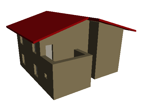
Here is an example of how it works in detail: Let’s see how to export the example image from the manual.
Choose the file name and disk location
A file with the file extension .ifc will be created. This file is in text format and contains a range ofparametric data on the design elements. Each Domus.Cad element is associated with a series of parameters such as the material used, the geometry, the plane on which it belongs, etc.
If the file is reopened with another compatible program, as a result of the IFC format, all of the necessary information will be transferred as well. The various programs will read the data in such a way as to make the introduction of the same data unnecessary.
Here is the result of reopening the file with any IFC viewer:
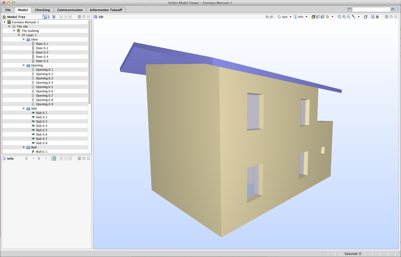
It is evident that the import was carried out correctly and that all of the elements have been appropriately interpreted.
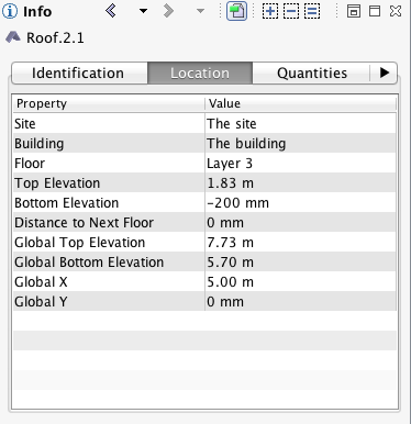
Let’s look at the characteristics of a roof pitch:
Thus, what was a pitch roof in Domus.Cad is still a pitch, retaining its characteristics. This feature is not featured in other export formats such as DXF or DWG. In fact, in the latter formats, we wouldlose the single element with its intrinsic characteristics, as it would appear as a series of faces positioned within the space.
Thanks to this format, it is possible to export elements in structural calculation programs, computing systems, etc…and retain all of the information entered on Domus.Cad.
From a conceptual point of view, the IFC format is similar to the AREF format. In fact, the latter is based on a common and conventional public protocol intended to provide a homogeneous reference for the interchange between different geometric information, topological and qualitative programsrelating to construction elements. This export format has been present on Domus.Cad since itsinitial versions.
The exported plans are those which are visible in the 3D window.
Before the export, Domus.Cad performs an optimization of the elements.
The slope is checked in the floors to determine whether it is a generic rooftop or floor.
Saving print information
Print information is now stored in both the document and in the preferences. This way, there is no need to choose the page size, orientation, etc every time. This feature was already present in the Windows version.
Modules
Three new modules and new features have been added to the Modules menu: Map2Cad, RoofTiles and Super2Dto3D.
Mac2Cad
Map2Cad is a module of Domus.Cad Pro and Std, which enables you to import both satellite and road maps from Google Maps.
Maps are imported with actual measurements and represented in the video scale selected in Domus.Cad.
The main features of Map2Cad are:
- Internal browser for viewing maps, with the Google Maps functions integrated
- Import of maps
- Managing a list of maps
- Inserting the maps from the list into Domus.Cad
- Maps are imported with actual measurements
The use of Map2Cad is very simple and allows for the integration of each of the Google maps features in Domus, including search functions, display choices, street view and more.
More information about Map2Cad >
RoofTiles module
This module allows you to quickly create a roof covering with Roman-style flat and curved tiles, using parameters. The result is a very detailed 3D model.
When you select RoofTiles from the Modules menu, the following dialogue window appears:
After confirming, as with all the other modules, an object appears bottom left that must be positioned using the mouse and accepted by pressing the space bar or ‘Enter’.
Here is an example of a roof with flat and curved tiles.
Super2D3D Module
The new Super2D3D module enables fast transformation of selected 2D elements (segments, polygons, circles, rectangles etc.) into 3D elements of various shapes and sizes.
It is particularly useful for rapid creation of gratings, railings, gates, metal supports, decorations and much more.
Here is an example to explain its use.
We begin with a 2D drawing.
It has an external rectangle 8 pixels thick, two internal circles 4 pixels thick and some lines 2 pixels thick.
If we select all of the elements and choose the Super2D3D module, the following window appears:
Each conventional thickness is associated with dimensions and a shape. The shapes available are squares, rectangles, circles and ellipses.
The module creates a horizontal or vertical 3D model, formed from elements that have the same section as the original.
Solid elements are also made solid in 3D.
The module creates an object, as with all the other modules, that must be accepted by pressing the space bar or ‘Enter.’
Based on the parameters in the drawing, here is the 3D result:
The central part is solid because the circle in the centre of the original drawing was hatched.
Another example:
Parameters of Super2D3D module:
3D view:
Super Pipe
In the event that the local origin option (blue axis) as the center of the profile is active, this is taken into account rather than the global origin option.
Now you can use a selection of segments, curves and polygons as generating elements instead of an individual polygon, as in the previous version.
The materials utilised in the object created are those of the selected generator element (the object created in the previous version had only one material, the current one).
Here is a more detailed example:
SuperRot
As with the SuperPipe module, the option to choose the relative origin as the center of rotation was added.
Furthermore, we can also use a selection of segments, curves and polygons as generating elements.
The materials used in the object created are those of the selected generator element (in the previous version the object created only had one material, the current one).
Here is an example.
It is possible to trace the profile using independent segments and polygons without the need to transform all of the elements into one polygon.
ObjectRot
This module allows you to rotate any object within the space. The center of rotation reference is the point (0,0) of the relative coordinates if these they are active, otherwise it is the zero point of the absolute coordinates. Previously, the only way to rotate the object in order to achieve a fixed height was to move the object and place it close to the absolute coordinates. With this new version you can use the center of the coordinates as the center of rotation. This possibility allows you to position the relative coordinates in the vicinity of the object without having to move it and obtain the requiredrotation.
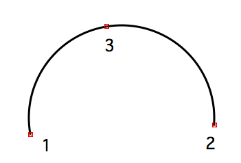
Inserting 3-point arcs
It is possible to insert an arc passing through three points, in a similar way to the introduction ofa circle passing through three points. For the introduction of circles and arcs, the icon for introducing the closed arc was replaced on the palette with the icons for introducing the arc passing through three points.
Mac os x Windows
If you want a closed arc, you can make the relevant selection in the ‘Polygon parameters’ window.
To obtain a three point arc, you need to click on the first point, move the mouse, click on the second point, and then finally the third. The first two points are the chord of the arc and the third point determines the center and radius.
Optimization of the zoom function on 3D views
By pressing the + or – button when the 3D window is active, you can nowobtain a linear enlargement or decrease regardless of the complexity of the 3D model.
Optimization for newer operating systems
Many verifications on newer operating systems (MacOs 10.11 for Mac and Windows 8.1) were carried out in order to improve the display and printing processes.
Pagination
You can now open the Pagination window directly from the toolbar by pressing the button:
Before, this button brought up the print procedure.
A double click on a paginated layer closes the pagination window and opens it as the active layer.
Real time image rotation
A new function has been added for images.
You can now insert the rotation angle for an image without using the pictRot module. In this way you can always go back to the original configuration by putting the rotation angle as zero.
To modify the angle, put the numeric value directly into the Parameters window:
Alternatively, you can modify the angle using the existing functions such as rotation, rotation on mouse click etc. And thanks to roto-translation you can now superimpose an image onto a drawing, with great precision.
Interactive messages drawing/modification
It is now possible to have certain details close to the mouse cursor while tracing or modifying some elements.
This option can be enabled from Domus.Cad Options menu->Domus.Cad Preferences, clicking on “Measures in tracing ”
In more detail:
For walls and segments, when being inserted or modified, the length is shown.
For stairs, the length of the step is shown.
For windows, when being inserted or modified, the length is shown, except when being moved or inserted with fixed width, in which case the distances between the outer edges of the nearest walls are shown.
Selection rectangle with intersection of elements
Pressing the ‘Alt’ key will change the selection rectangle to a blue color. This signifies that we are in selection-with-intersection mode.
Here, if just one side of the selection rectangle intersects an element, this is sufficient for it to be selected, once the mouse button is released.
This function can be used along with the other function keys as for selection with normal rectangle.
To sum up about the selection rectangle:
- No key pressed: All elements, and only those that are inside the rectangle and are of the type shown in the icon pressed in palette 1, are selected.
- Alt (option) is pressed: All elements that intersect with the selection rectangle and are of the type shown in the icon pressed in palette 1, are selected.
If the ‘Command’ key on Mac or ‘CTRL’ key on Windows is also held down at the same time, the selection is extended to all elements, regardless of the icon pressed in palette 1.
If the shift key is also pressed, the elements are added to an already existing selection.
Get properties
Right-click with the mouse (CTRL+Click on Mac OS X which only has one button). A menu appears from which you can choose “Get properties”. This option is only enabled when there is an element selected.
It automatically sets all of the properties of the selected element for new elements. The palette icons will be set automatically according to the element selected.
Dynamic text sizing
If you have a selected text, you can increase the font size by one unit by pressing “Command +” (Mac) or “CTRL +” (Win). To decrease, press “Command -” (Mac) or “CTRL -” (Win). This works in a way similar to text modification on browsers or e-mail clients.
If nothing is selected, you move up or down a level, as before.
Rounding polygon corners
You can now round polygons with Bézier curves.
This new function can be used on both existing and new polygons.
Rounding is controlled by the cursor Smooth inside the Polygon dialogue window.
The coefficient of rounding can be defined using the Smooth slide-bar, you can increase or decrease the coefficient of rounding to obtain a more or less pronounced curve;
If, for example, we take a rectangle:
No rounding:
Medium rounding:
Maximum rounding:
The curve can be increased by adding intermediate points to the polygon:
If a rounded polygon is transformed into a slab, it will give an element with a very great number of vertices. The same goes, if using the extrusion function or modules involving polygons.
New instruction manuals and new videos
The instruction manual, which can be found directly from within the program (via the “Help” menu on mac os x and the “?” menu on windows.), was updated.
Videos equipped with audio were added to the instruction manual, so that they can be viewed at any time without having to exit the program.
The videos are short tutorials that describes many situations ranging from the most basic operations such as the insertion of walls to complex situation, such as the advanced use of the modules.


