


Domus.Cad 26 (soon)
Differences from version 25.1.3
Cloud Groups
Point clouds can consist of hundreds of millions of points.
This is generic unstructured information, the points are all at the same level, regardless of whether they belong to a wall, a roof or a parked car that only creates problems.
Cloud Group management has been introduced in Domus.Cad 26. Cloud Groups allow you to organize the point cloud and give it a structure by dividing the various parts. The groups thus created can be visible, invisible, they can be joined together, erased, simplified and separated.
This allows, for example, to work quickly on the various parts with a clear visualization of what is needed at that moment.
The groups that make up a point cloud are visible by clicking on the More buttoners at the top right of the Cloud panel.
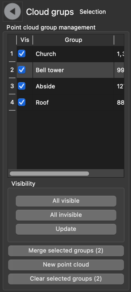
This table allows you to do the following operations:
- Making groups visible or invisible
- Merge multiple groups into a new group
- Delete groups
- Create a new point cloud, independent of the original one, with the selected groups. This way you can detach a group of points from the original point cloud and move them, rotate them, process them independently
Create groups
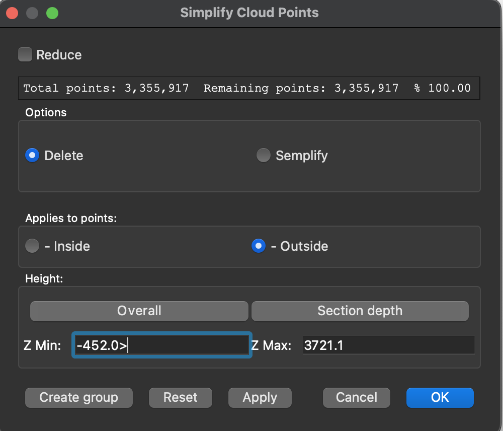
New groups are created via the Simplify Cloud Points window, which can be called with the button

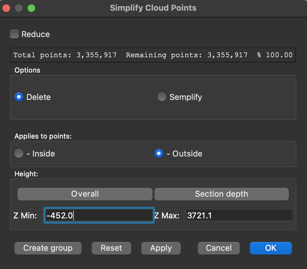
The window to simplify, delete and group the points of a cloud
The Create Group button has been added, creating a new group containing the points currently visible.
The steps of the operation are as follows
- Drawing of a two-dimensional or three-dimensional figure in plan, to delimit the area for the new group.
- Selecting the figure and cloud and opening the window Simplify Cloud Points
- Choosing interior, exterior point options Clear or Semolify
- Click Apply to view the points that will make up the new group
- Click on Create group and name introduction
- Click OK to confirm the group definitively
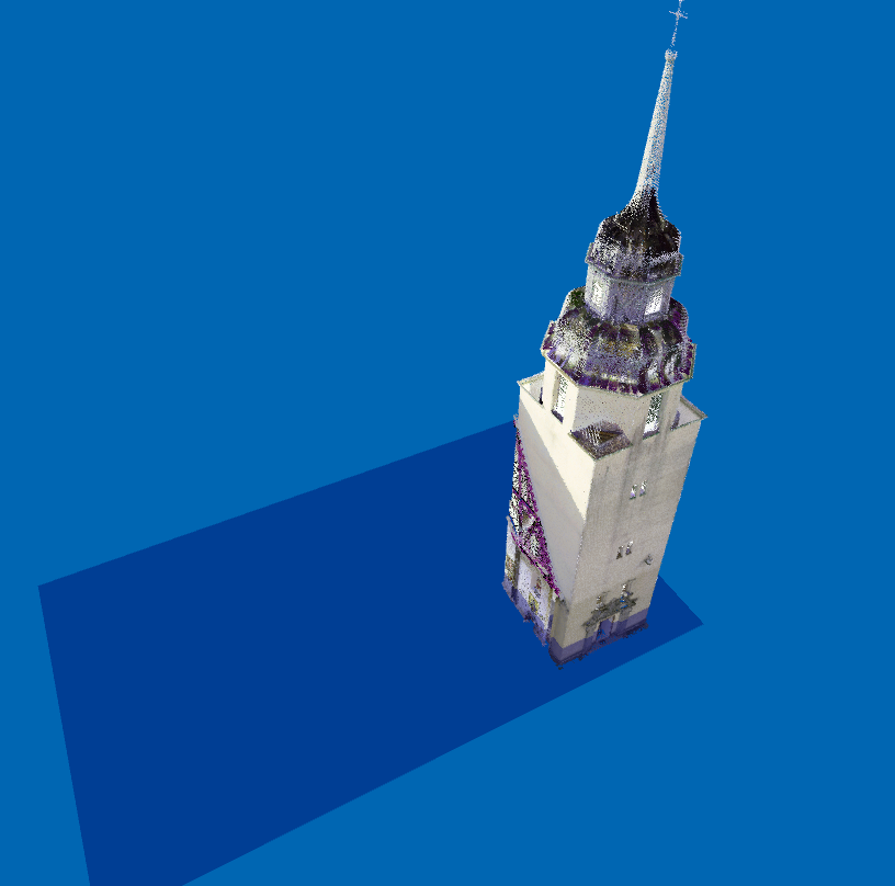
Example
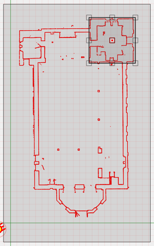
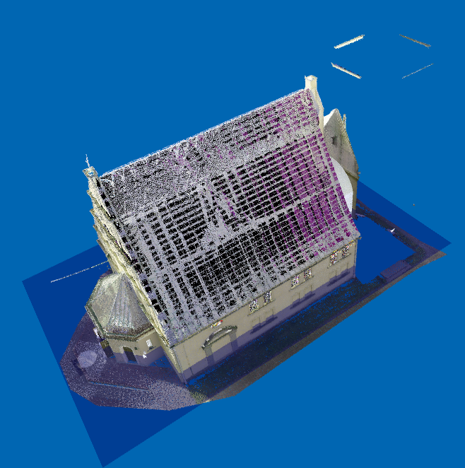
Let’s start with the classic church example in the program’s examples folder.
We draw a rectangle around the bell tower and select both the church and the rectangle at the same time.
We open the simplification window set as follows and click Apply.
We click on Create Group and assign a name.
The actual group is created by clicking OK.
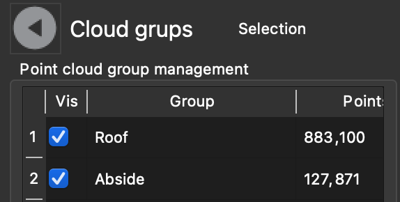
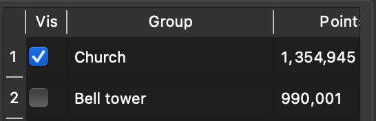
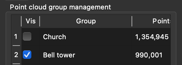
After creating the group, the group table looks like this:
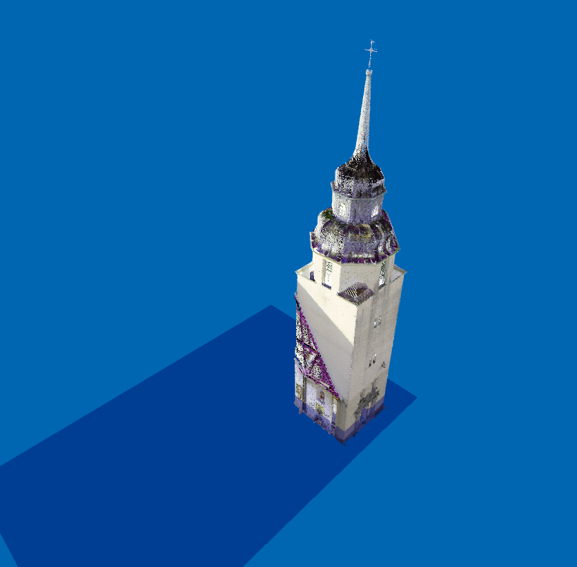
I can view the church without the bell tower:
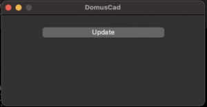
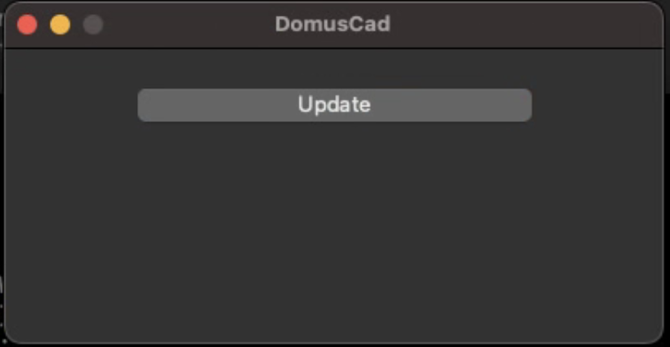
Press the Update button
Press the Update button
In a similar way, other groups of all parts of the structure can be created, such as walls, roof, apse, nave, altar, etc.
Advanced materials
In addition to basic material management, advanced material management has been introduced, which can be used in OSPRay quality rendering. However, these materials also have a basic representation that is represented in interactive fast rendering.
The new materials are:
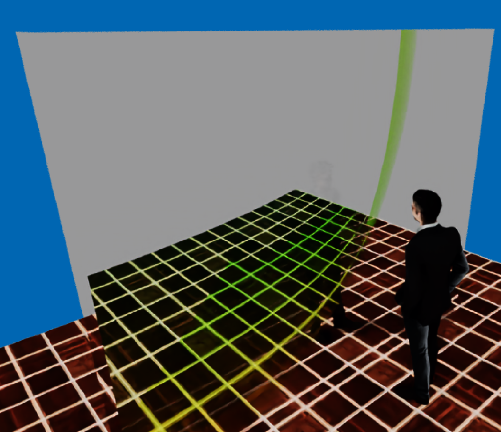
- Metals: aluminum, copper, gold, silver and copper. They are characterized by a degree of roughness or luster and can be engraved with images.
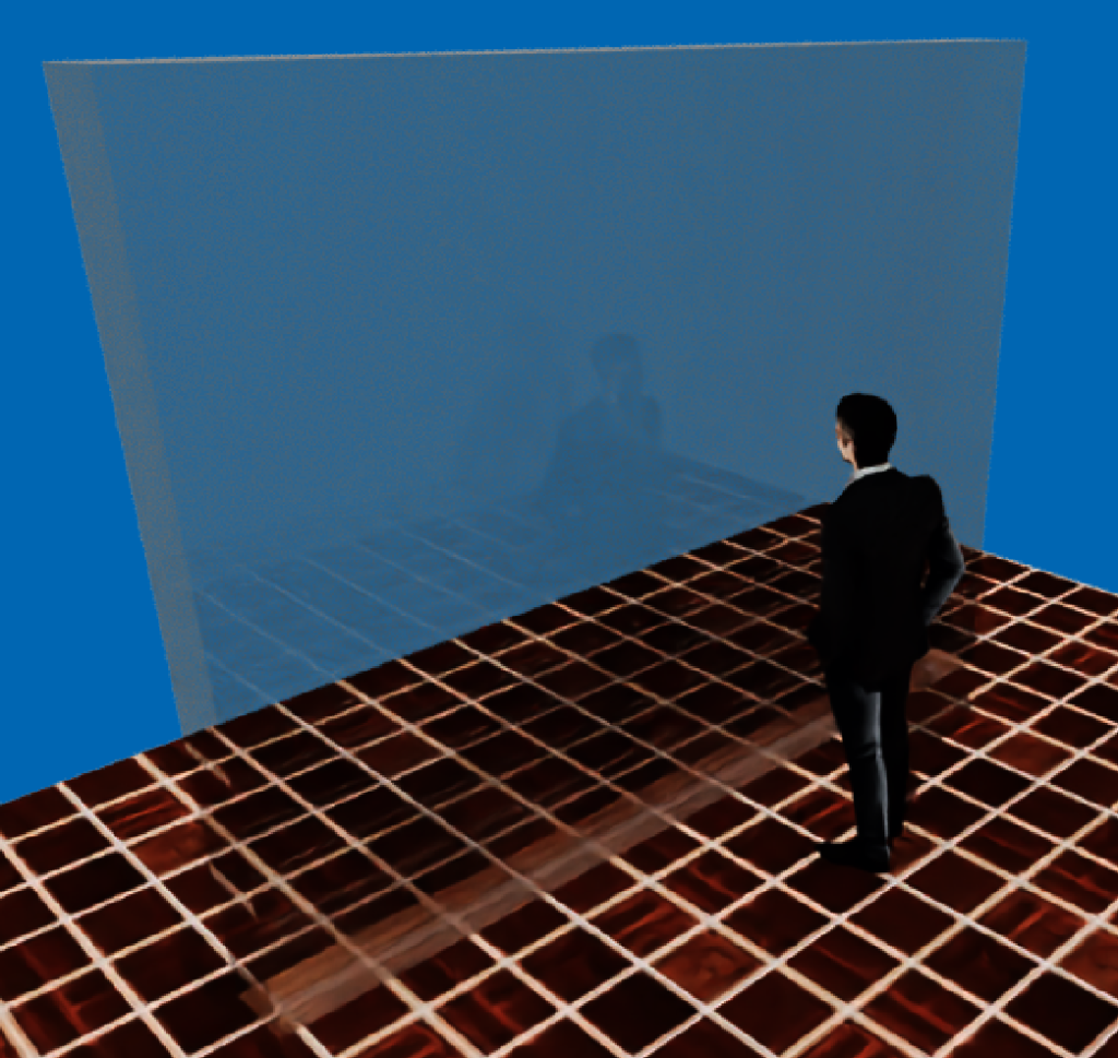
- Glass. Beyond color has a refractive index
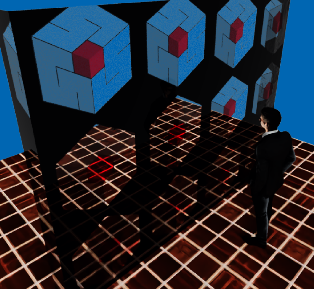
- Thin glass. It also allows you to apply colors via textures
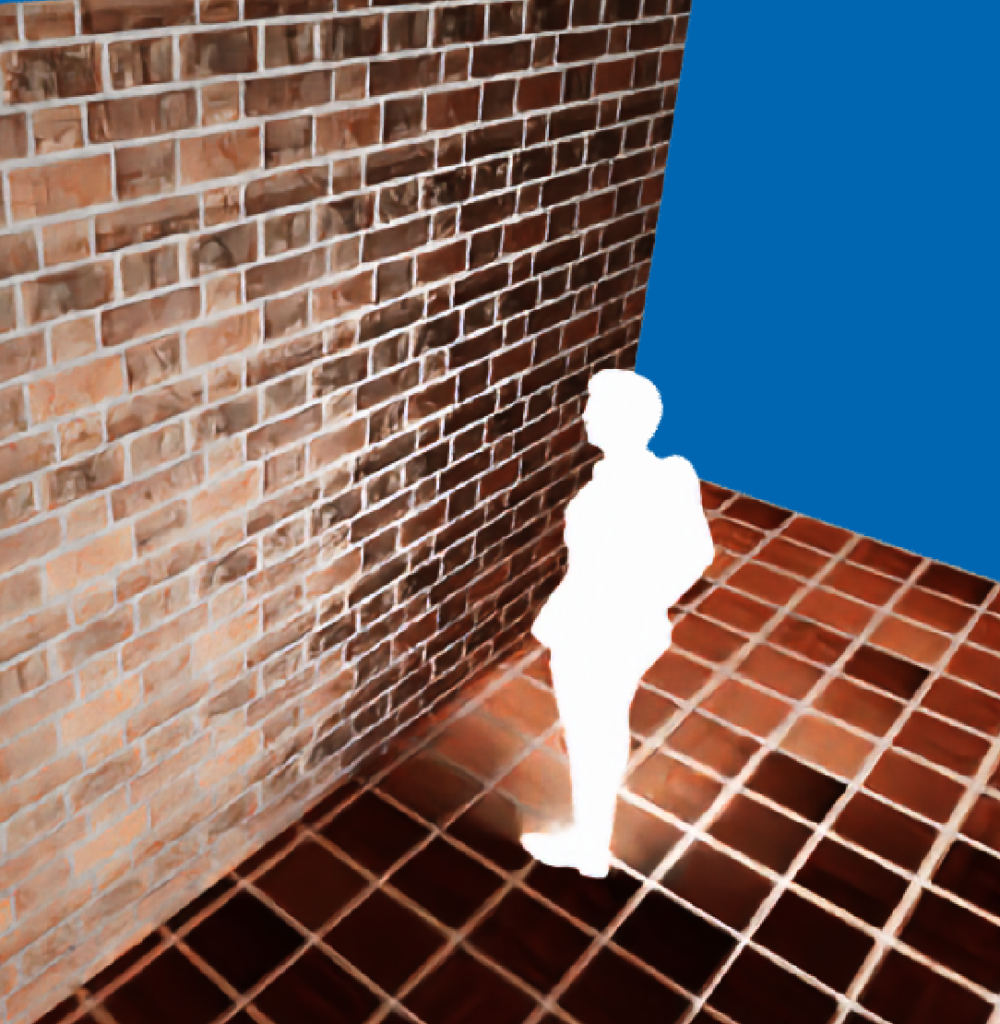
- Luminous. It is a material that twins light
Materials dialog
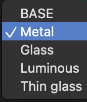
The materials dialog has changed as follows:

For each material, a menu allows you to indicate the type of material.
The base material is the one also present in previous versions and is defined by the values on the row, such as material color, mirror color, transparency, etc.
For other types of material, some other information must be entered.
This information appears at the bottom of the table when the material row is selected on when choosing the material type from the menu on the right
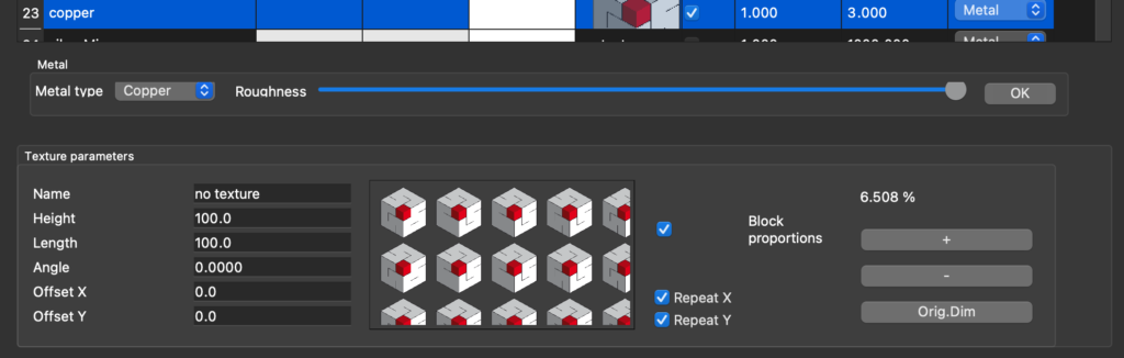
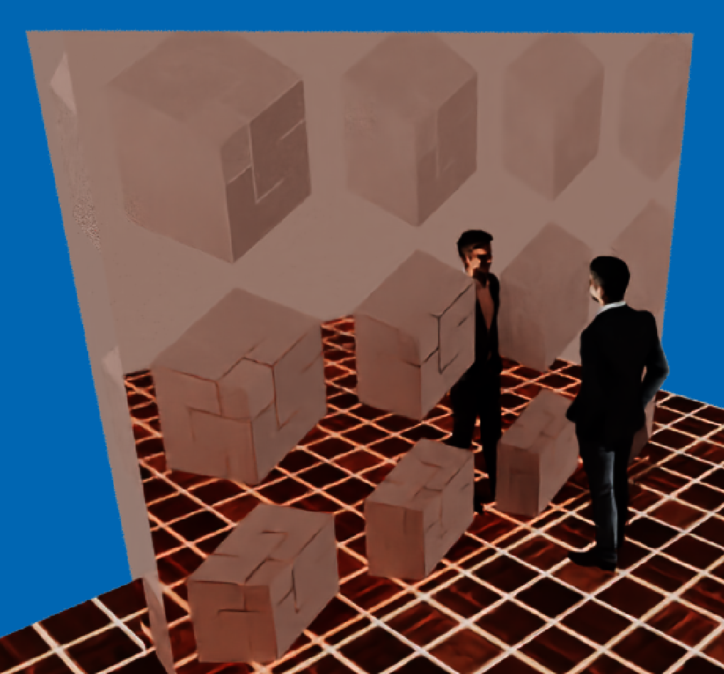
Metals
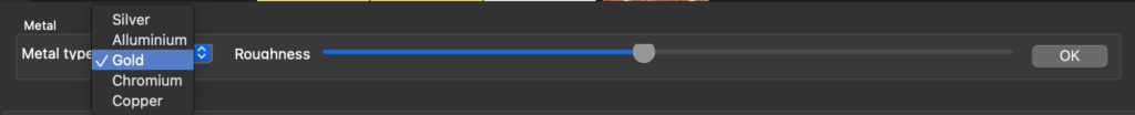
The menu allows you to choose the metal and the cursor the roughness.
Metals materials are not affected by the basic parameters included in the material list, with the exception of texture, because they have their own specific characteristics. However, it is good to give similar colors and specifications so that the representations in interactive fast and in advanced rendering are similar.
Some examples of metals follow.
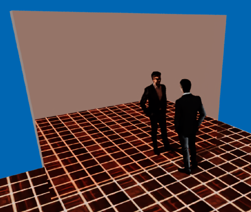
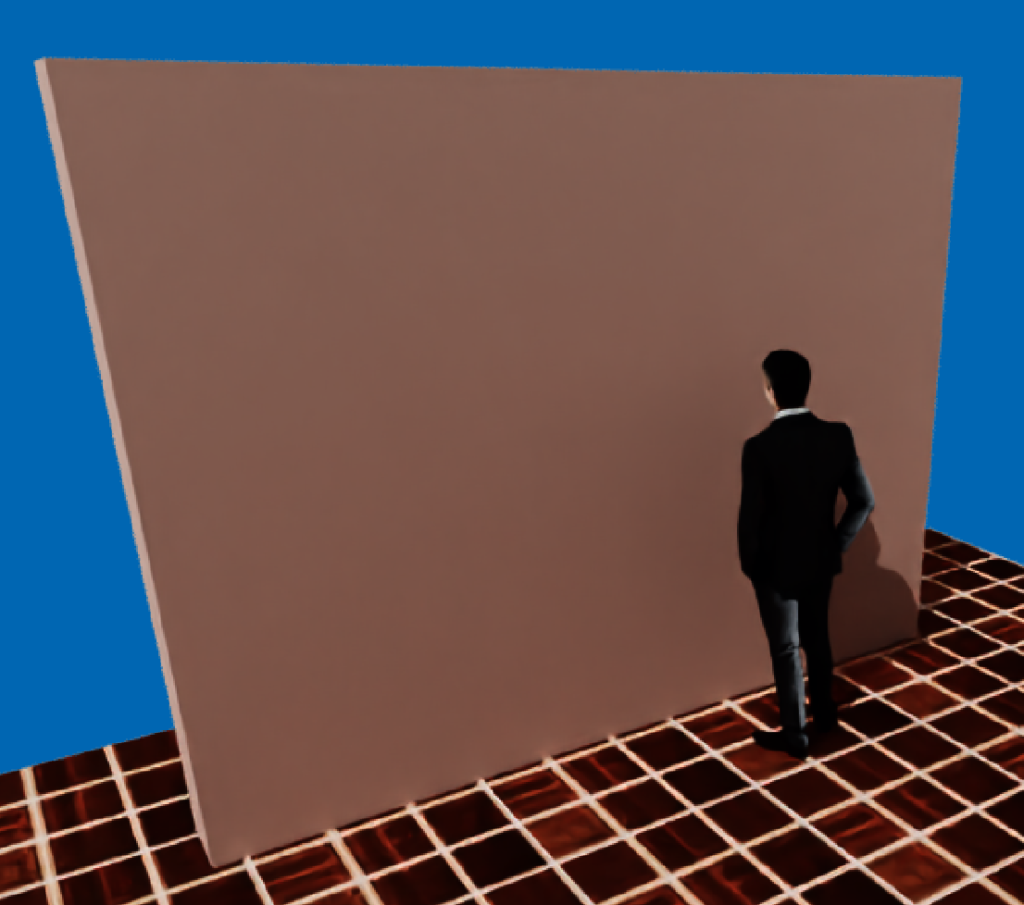
A texture can be applied to metals, but it is not colored as in the base material, but it impinges on the metal, making the rough parts shiny.
Glass
The parameters of the glass material are:
- The refractive index. It must be a value less than or equal to 1. Values lower than one produce image deformation beyond the glass.
- Attenuation color. The light passing through the glass is attenuated according to the color of the attenuation. If the color is white there is no attenuation
- Attenuation distance. It influences how the image behind the glass is attenuated and deformed.
Textures are not applicable to glass material.

Thin glass
Thin glass is a suitable material for stained glass windows and elements such as bottles and glasses
The parameters of the thin glass material are:
- Refractive index. In this case it can have values both above and below 1.
- Attenuation color. Light passing through glass is attenuated based on the color of the attenuation. If the color is white there is no attenuation.
- Attenuation distance. It influences how the image behind the glass is attenuated and deformed.
- Virtual thickness. It is the thickness of the glass used to deflect light based on the refractive index.

Luminous
With this material, therefore, it is possible to create an illuminating body of any shape.
Move and organize
Materials to the table intent can be moved and rearranged. To change the position of a line with a material, press the mouse on the order number on the left and drag it to the new position.
Change materials
This new feature allows you to view the materials used in the project and change one material for another in all elements of the project.
The function is accessible from the Options->Change Materials menu or by clicking the Change Mat button in the Advanced Rendering window and the CM button in the interactive rendering window..

Clicking on one of the material cells displays a menu that allows you to change it to any of the available materials.

Brightness – Contrast
This command opens the dialog to change the brightness and contrast parameters of a selected image.
The function is accessible from the Process->Brightness – Contrast menu and the Brightness – Contrast button in the image management panel.

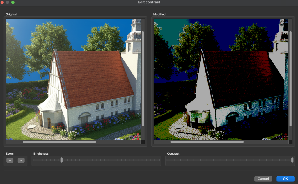
The left pane shows the original image and the right pane shows the image with the new brightness and contrast parameters.
Fast update
When the program starts, if connected to the Internet, it checks if there is an update compared to the current version. If the update version is later than the open program version, the following dialog box appears.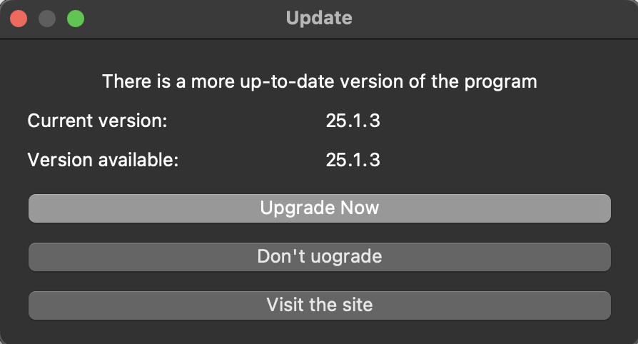
- Upgrade Now. This button immediately updates. The following window app
- Continuing with Update Domus.cad closes, the update is downloaded and installed, and then the program opens again. This update only downloads the application binary file, it does not update the entire package with examples, libraries, manuals, extra material.
- Don’t update. Il programma va avanti senza aggiornare.Visita il sito. Accede alla pagina di download, dove è possibile scaricare l’intero pacchetto e il materiale extra.
- Visit the site. It goes to the download page, where you can download the entire package and extra material.
The fast update can be performed at any time from the Help menu.
Axial deformation polygons
Axial deformation was also activated when modifying the polygons.
By changing a vertex with the active axial deformation option the vertex moves along the extension of the side preceding the vertex for all vertices excluding the first one or at 90 degrees to them. The first vertex moves along the extension of the next side.
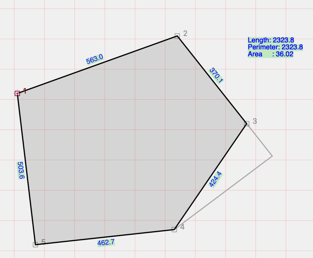
Deformation of vertex 3 along direction 2-3
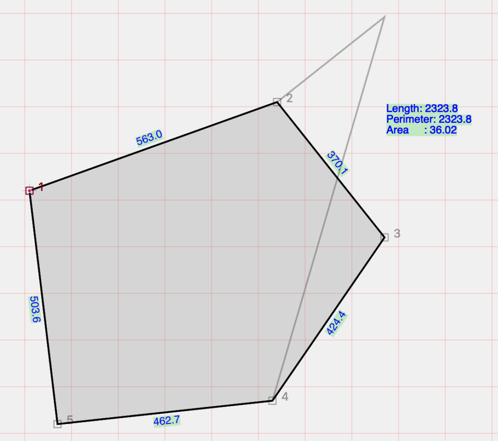
Deformation perpendicular to direction 2-3
Reversing walls
This new function swaps the inner and outer faces of the selected wallsi
Improvements
- Enabled selection of the last tracked element in the case of segment tracking with 2 clicks
- Cut mode remains active until you press esc or click another icon
- In case there is only one handle selected (with the item not selected). With the arrow keys it is translated by the current step, if I press “p” I go to the previous vertex and “n” to the next vertex
- Forced element type nullification when regenerating 3d model
- Transparency management editing digital coordinates. Improved visibility of reference markers
- When reading the added model the ability to exclude all textures if it does not find them
Error corrections
- Correct error in creating the PDF of the drawing table
- Fixed undo/redo edit from Camera panel
- Fixed undo/redo projection type
- Fixed trimemesh texture offset
- Actual deletion of stratigraphy polygons when I turn them off. Previously, there were empty polygons left when the file reopened.
- svg export now works.
- Calculating element numbers now also considers the elements contained in the dxf and dwg
- Now it is no longer possible to put itself as a background plane
- Added the number of point clouds in the info
- Correct floor with dimensions. In some the attic dimensions were incorrect.
- Fixed UNDO/REDO of manually entered polar and relative digital coordinates
- Polar coordinate editing with preview in the plant
- Fair oriented aperture faces in export.
- Exporting pyramids and cones ok
- Simple slabs correct orientation and mapping
- Correct normal oval-niches
- Export Niches corrected face normals
- Fixed export assimp glb, gltf
- Automatic update added dialog
- 3d dwg model export fixed bug duplicate names