


Design fast with Domus.Cad

The first part of the article describes point clouds and how Domus.Cad manages them. This is followed by tutorial videos showing how it is done in practice. See also the special offer for users of other CADs.
Point cloud surveying and management is becoming increasingly important in architectural surveying and design.
Survey systems are increasingly widespread and diverse, ranging from classic laser scanners, drones, simplified Lidar systems and smartphones with built-in Lidar sensors.
All these systems ultimately allow us to detect a series of colored dots, which, seen from a certain distance, allow us to see and recognize the object of the survey.
These images of a point cloud are composed of a few hundred million points which, when viewed from a certain distance, appear compact
Structureless survey
Architectural or topographical surveys performed with traditional instruments, from the classic metric cord to total stations, are well structured, not detected at random, but precise architectural elements such as edges, vertices, positions, etc. are measured.
Point clouds, on the other hand, do not have a real structure, but only an apparent and visual one. When a laser scanner detects a building it makes no difference between a vertex, an edge or any point in the middle of a wall.
The same building as the previous figure, but with the camera very close to the cloud. On the right you can see the individual colored dots, detached from each other. The information is not structured.
To use a point cloud in architecture, it is therefore necessary to give structure to the chaos, transforming indefinite masses of points into walls, doors, floors, roofs, stairs, floors, etc., so as to then continue with the subsequent design.
From Chaos to BIM with Domus.Cad
In this article, we go deeper into Domus.Cad’s advanced features for integrating point clouds into your program, simplifying them, quickly identifying their constituent parts, and inserting BIM elements that perfectly match cloud point groups.
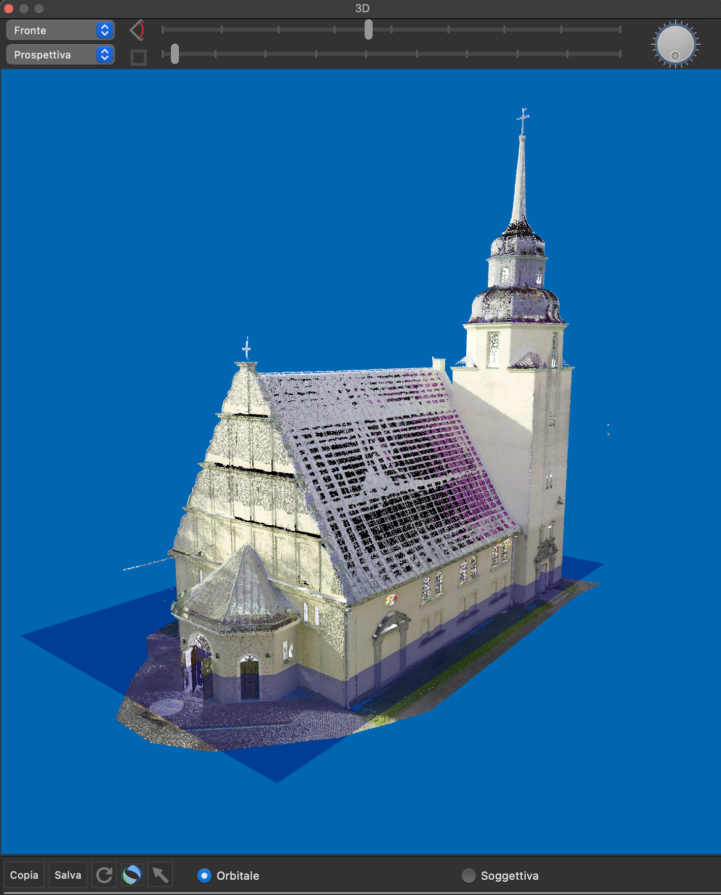
The point cloud of a church
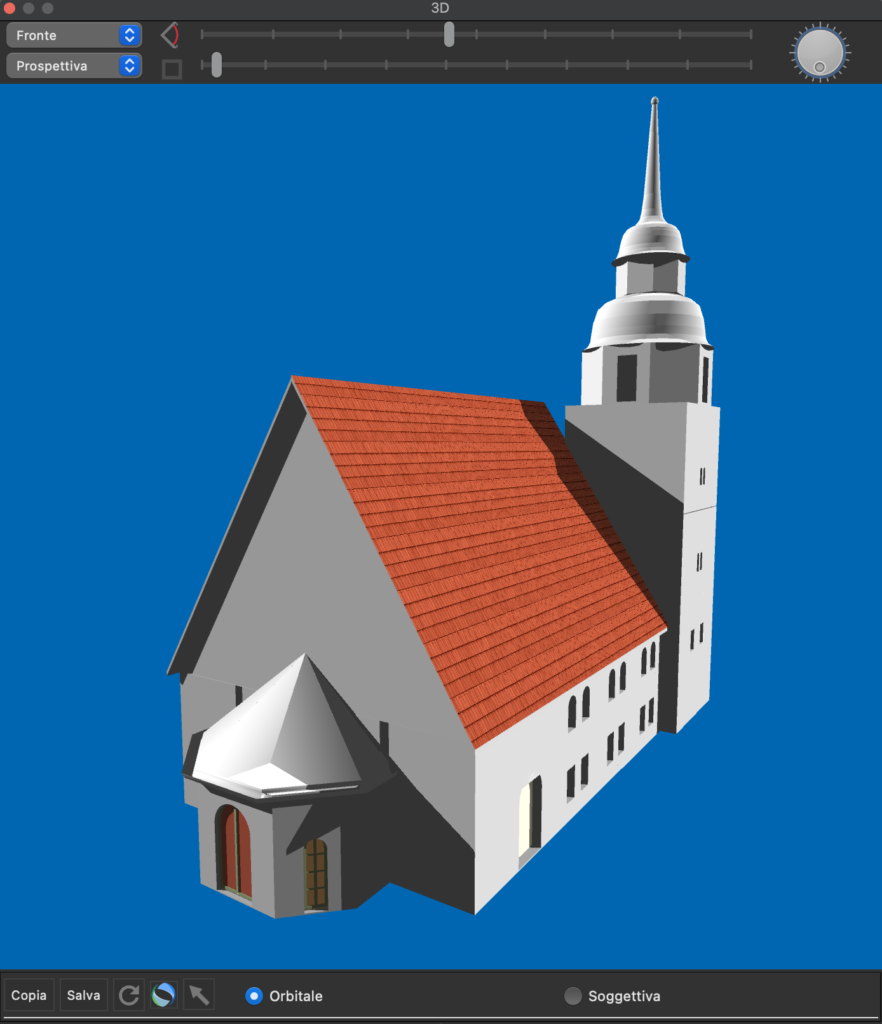
BIM model derived from the point cloud, composed of parametric elements, walls, floors, roofs, windows, doors, etc.
Integration
For Domus.Cad, point clouds are basic elements just like the other elements of the program: walls, doors, roofs, slabs, stairs, etc.
All possible operations on the other elements can be done directly on the point clouds, for example, rotations, translations, scaling, duplications, etc.
Like all other elements, point clouds have their own management panel, where the various parameters are changed in real time.
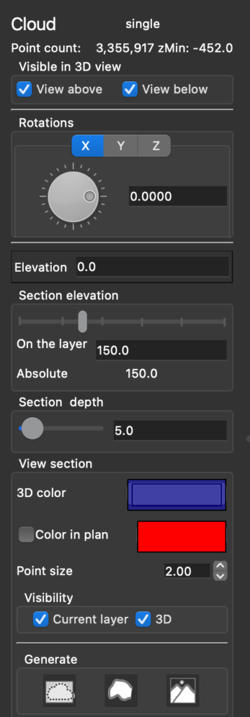
The Point Cloud Control Panel
This means that there are no different ways of operating and everything is much faster.
Multiple clouds
Domus.Cad can set and handle any number of point clouds. This also allows you to import surveys performed with Lidar sensors with limited range, such as those on iPhone Pro. By putting the various groups of clouds together, an entire building can be composed.

In the figure above inside an office detected with an iPhone Pro
Simplification
When scanning points across multiple positions, there are parts taken from a fixed position, others from multiple positions, or taken from a moving sensor, as in the case of an iPhone Pro. There are therefore areas where the detected points overlap and others in shadow that have not been imaged.
This inhomogeneity unnecessarily increases the heaviness of the Point Clouds. Domus.Cad has a series of interactive tools to erase, thin out, make visible or invisible, isolate parts and groups, and represent information in various ways.
A filter can already be used at the import stage according to the desired accuracy.
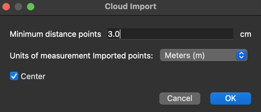
A filter distance can be set during import, in figure 2 cm. The distance is set based on the desired accuracy in continuing the work. All points closest to each other in this distance are not imported
Simplifying Cloud Points. This tool operates on parts of clouds, delimited for example by polygons or volumes, performing further operations, such as filters, erasures, visibility or invisibility, isolation of specific parts.

This panel allows you to act on all or part of the point cloud, simplifying, making the points visible or invisible, highlighting the parts where to operate and more
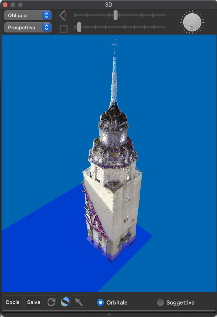
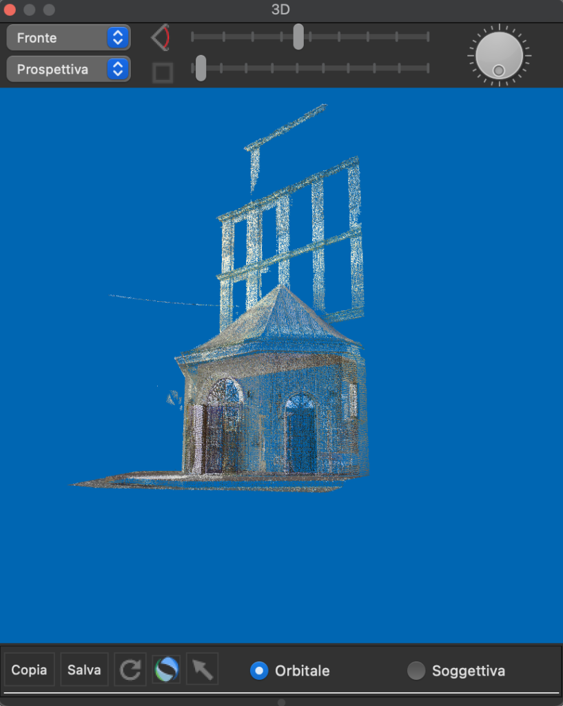
Only the bell tower was made visible from the church
In this case the parts outside the bell tower are shown with a lower point density and therefore with a lower density
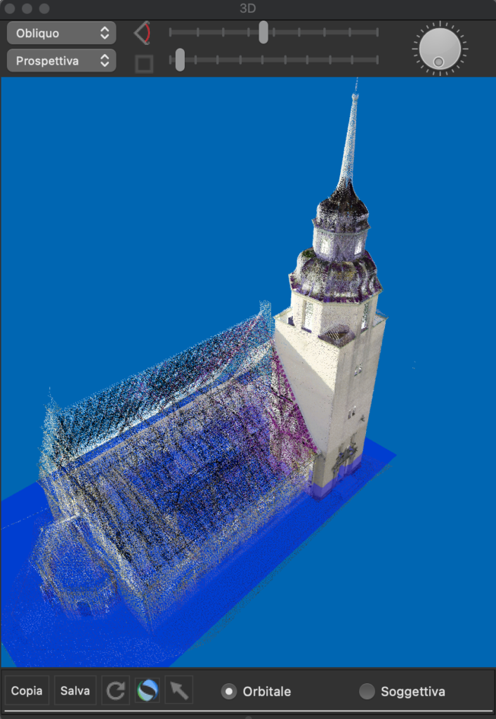
In the figure above the apse has been isolated from the rest of the church
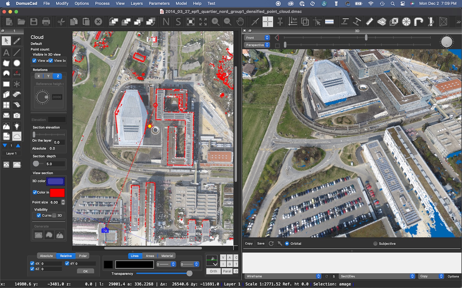
Interactive vertical bounding planes. Two planes perpendicular to the direction of view, freely movable with the mouse or numerically, allow you to view only the parts between the two planes. This allows you to very quickly isolate the parts of the cloud on which we want to intervene, such as a wall, an architectural element, a decoration, or anything else.
 The positions of the minimum and maximum lines represent two planes perpendicular to the direction of view and which can be moved with the mouse. In the 3D window only the portion of the model between the two planes is shown
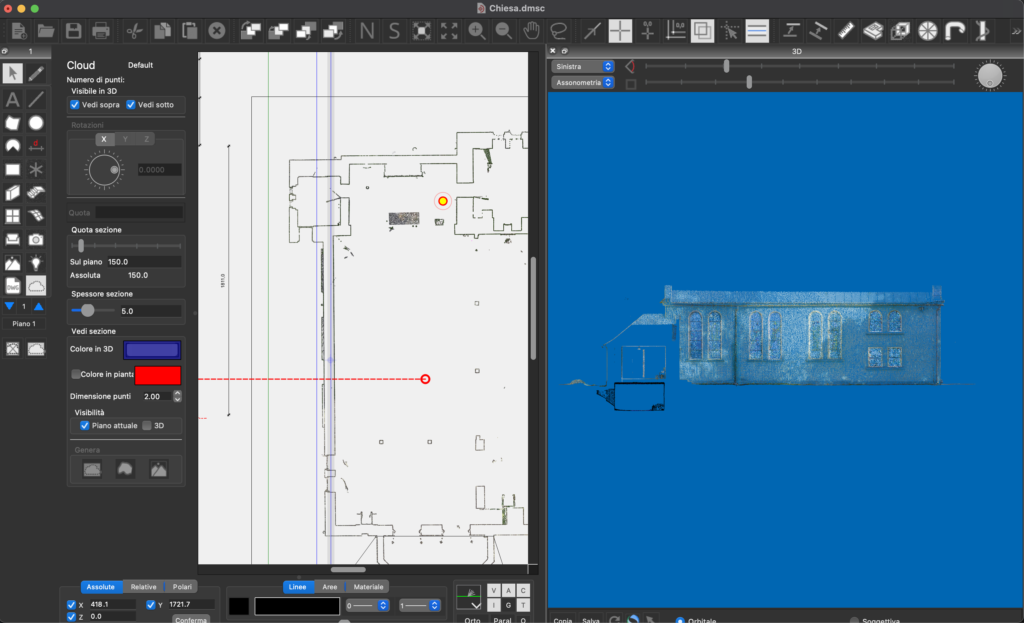
By positioning the two vertical planes of the minimum and maximum chamber with the mouse, only the points between them are represented. The two planes move in plan with the mouse so as to clearly identify the useful parts of the building
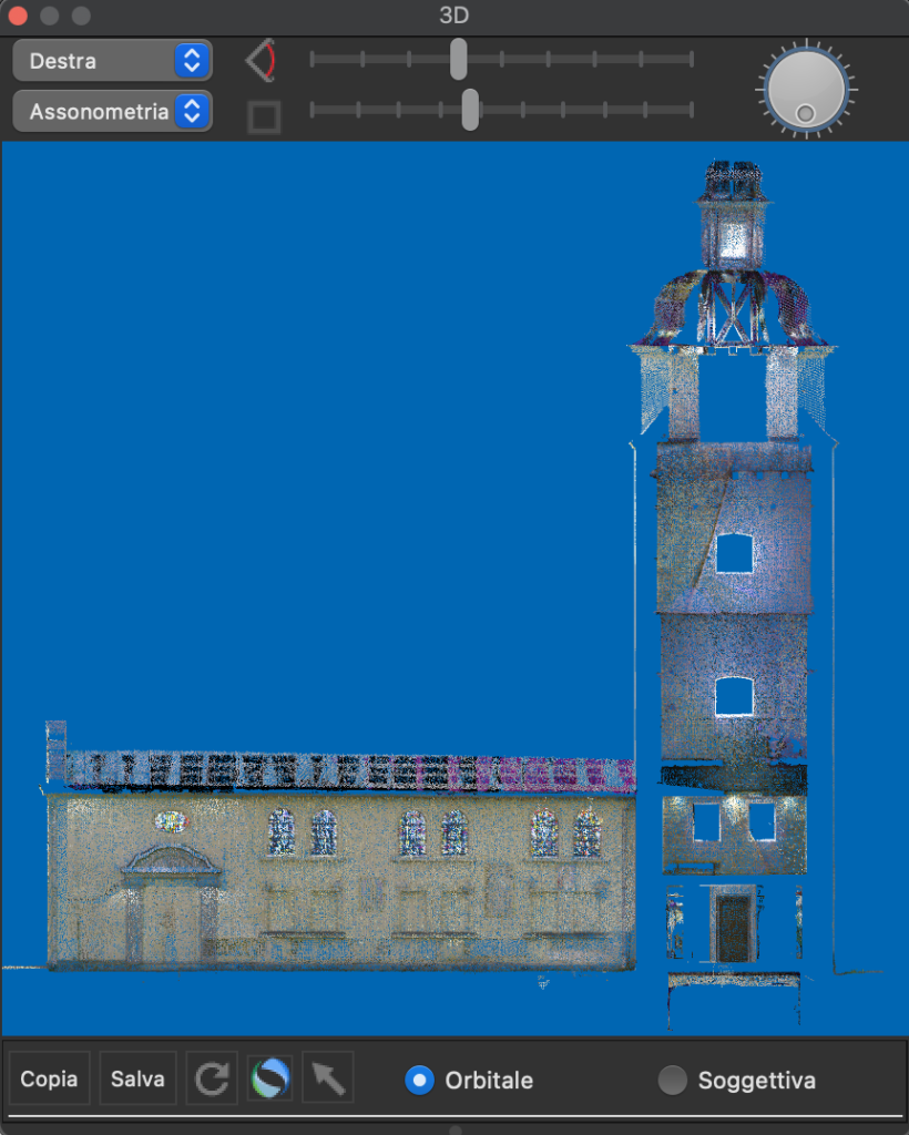
The same operation performed on the opposite wall
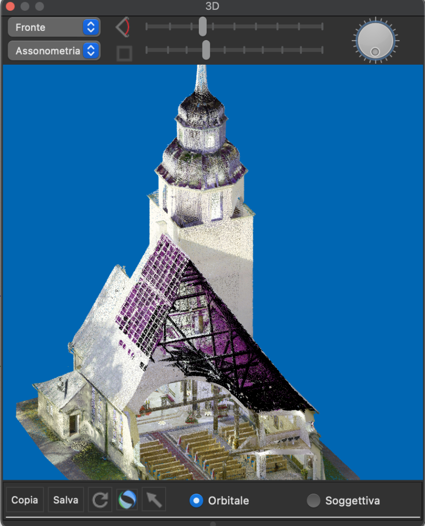
The two minimum and maximum planes are perpendicular to the direction of view and in the figure above they have been positioned to perform a cutaway
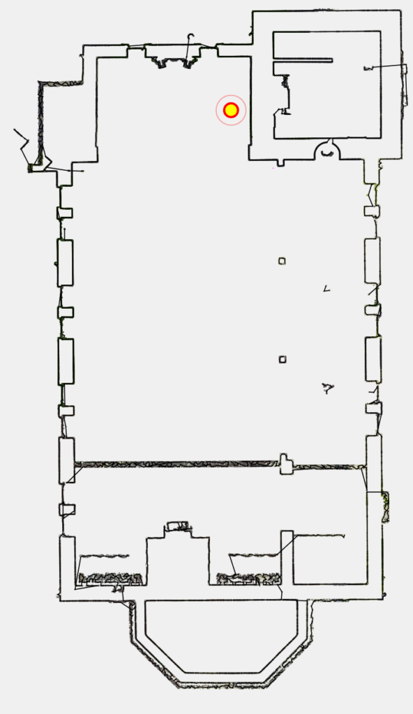
Organization in the building floors. When a point cloud is imported into Domus.Cad, it is immediately organized into the different floors of the building, so that they can be seen in plan and 3D, both as an overall building and floor by floor, thus concentrating where we are operating.
In the figure, the view of what is above the horizontal sectioning plane has been disabled and this allows you to see inside the plane
Vector sections everywhere.Dividing into layersd and managing vertical planes already generates immediate vector sections everywhere. Vector sections are composed of polygons and can be managed with Domus.Cad’s CAD tools.
From cloud to BIM
Architectural BIM elements, such as walls, doors, windows, stairs, floors, roofs, furniture and others, are inserted into the cloud with continuous and immediate control between the inserted element and the corresponding points.
The display and simplification functions referred to in the previous points allow you not to see all the parts that are not of interest at that moment. For example, if I’m inserting a wall with its windows, I can make it so that I only see the points in the cloud corresponding to the wall.
These operations are performed interactively, meaning I see the match in plan and 3D as I track the elements.
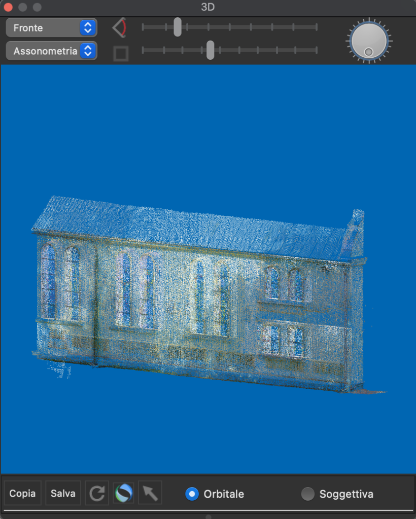
The part of the cloud corresponding to one wall of the church is shown highlighted without the rest of the building
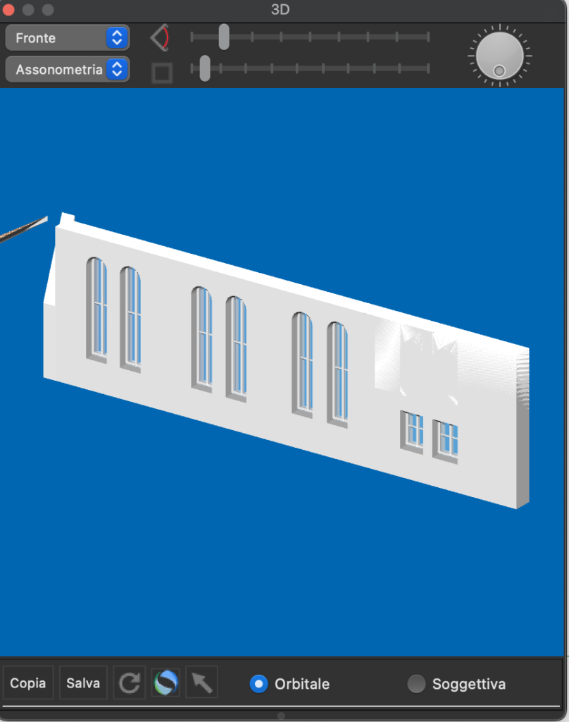
The same wall composed of walls elements, openings and fixtures, traced by matching the elements of the point cloud
The BIM elements, walls, openings and fixtures, exactly superimposed on the point cloud
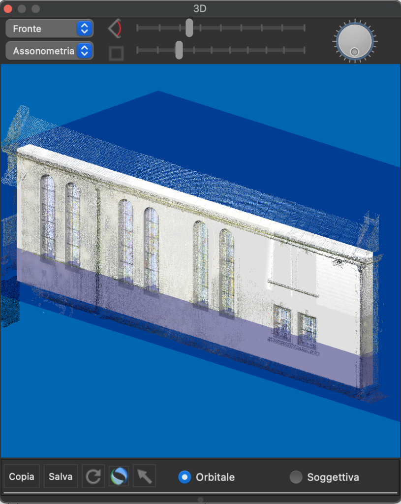
The same wall composed of walls, openings and fixtures, traced by matching the elements of the point cloud. The immediate and interactive display of BIM and cloud elements while they are inserted and modified, allows for immediate synchronization and correspondence between the two parts. Any discrepancies are immediately clearly visible and editable.
Automatic vectorization. It is simple and immediate to obtain vector drawings of any section in plan, vertical or inclined in any way. Vector designs are made up of polygons, which can in turn be transformed into other elements such as slabs, roofs, walls, etc.
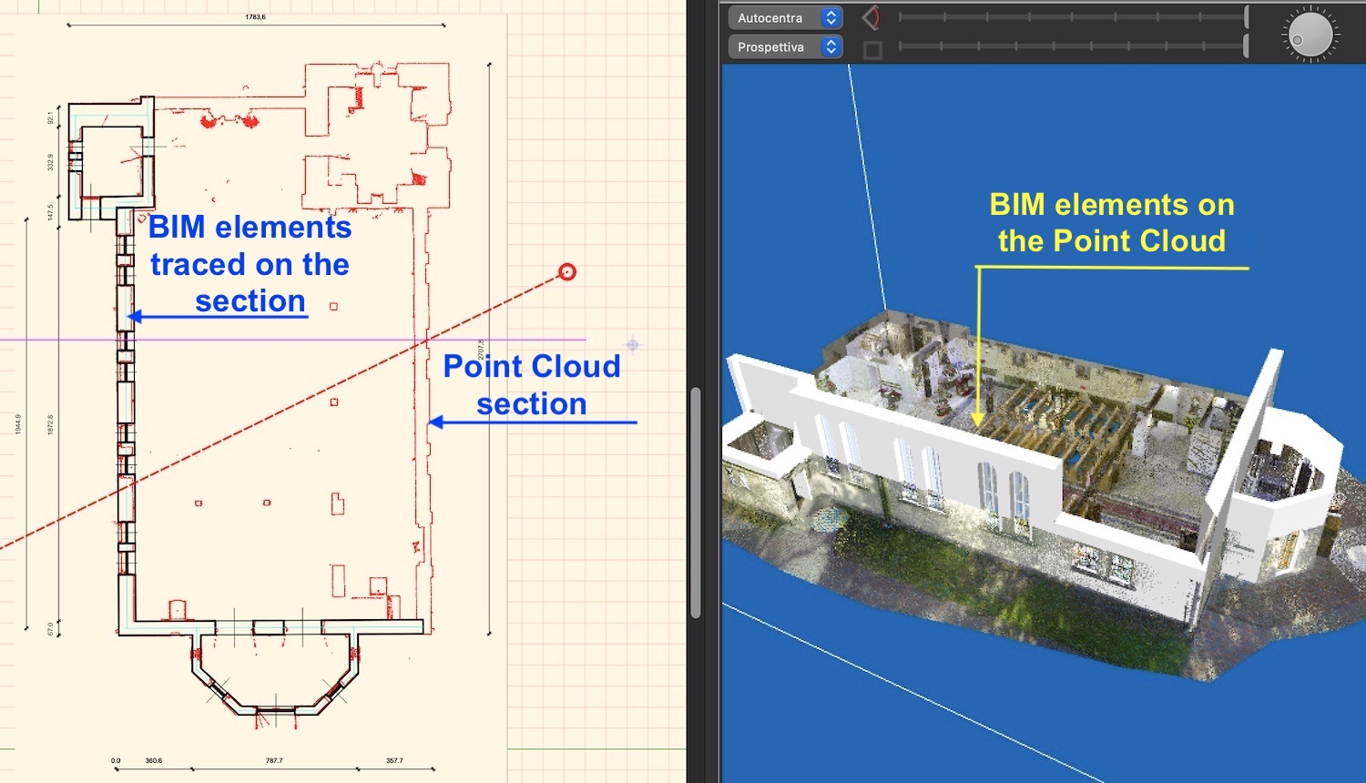
The plan is in practice a horizontal section at a height chosen by the designer. It can only be a section or have elements in view as in the figure in the next paragraph
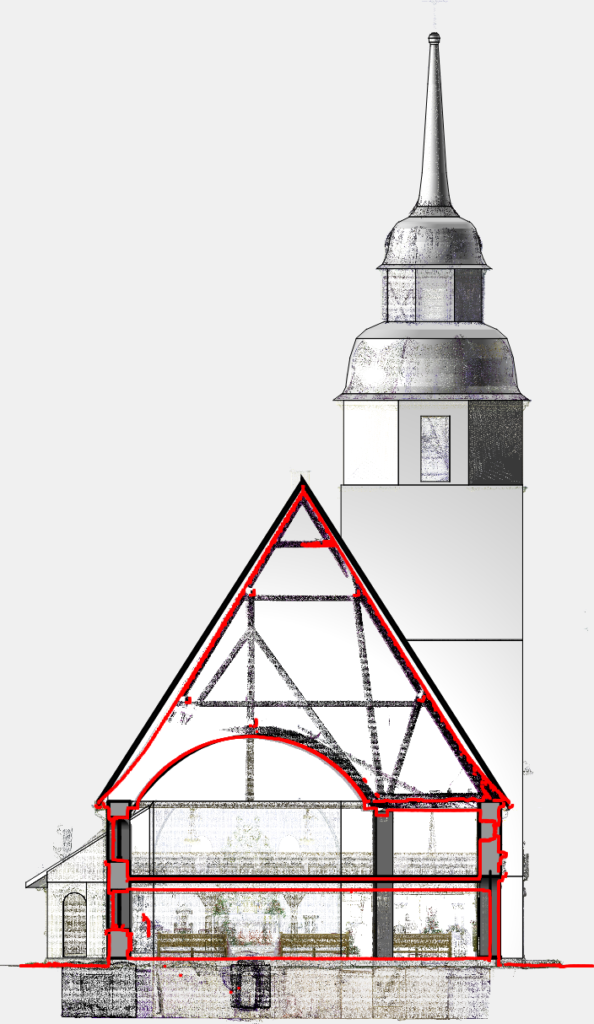
The cloud section, in red, superimposed on the BIM model section;, in black and on the point cloud behind the section plane
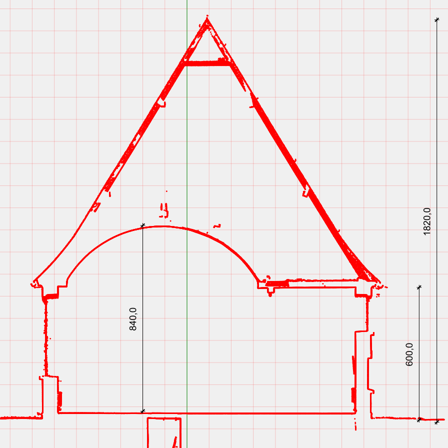
Dimensioned section
Scaled raster images. With a simple click of the mouse, you can generate exactly scaled and referenced images of plants, elevations, cross-sections, views, sections, etc. These images are in register with the points of the cloud and the elements extracted from it. Scaled image management is very useful with very large point clouds, centered by millions of points, because the memory occupied for operations is much smaller and all operations are much faster, this allows you to manage large point clouds even with non-latest-generation computers.
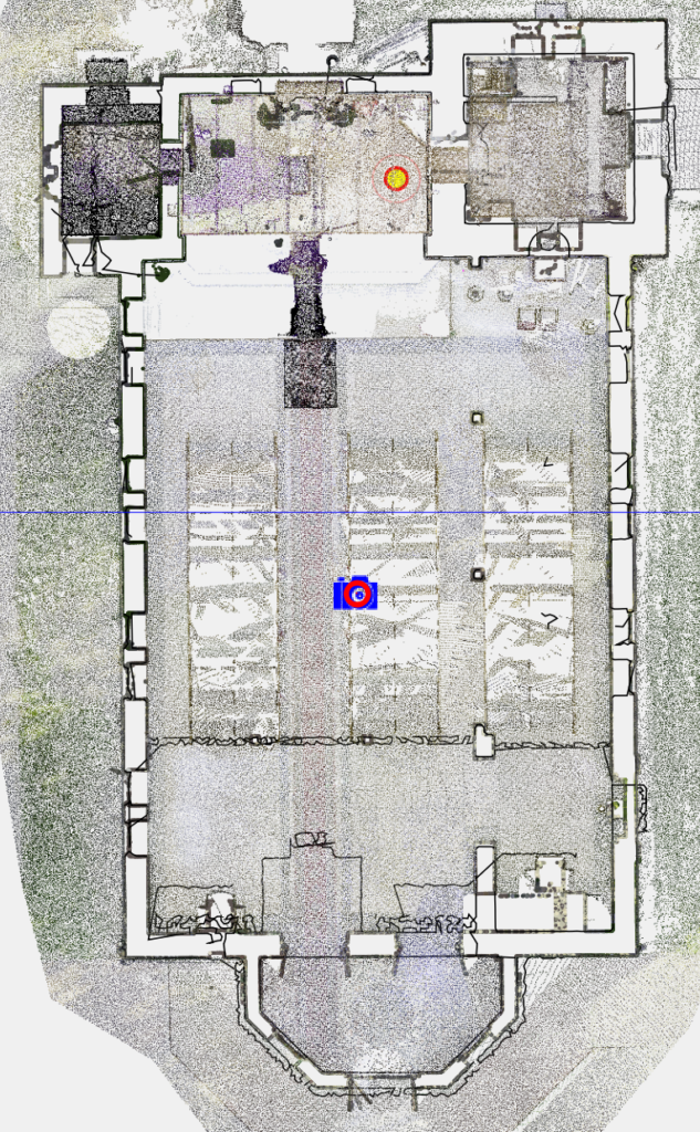
The image of the part of the cloud corresponding to the ground floor is superimposed on the horizontal section of the plan and the BIM elements. The image uses far fewer resources than the interactive representation of a few million points and allows you to work quickly
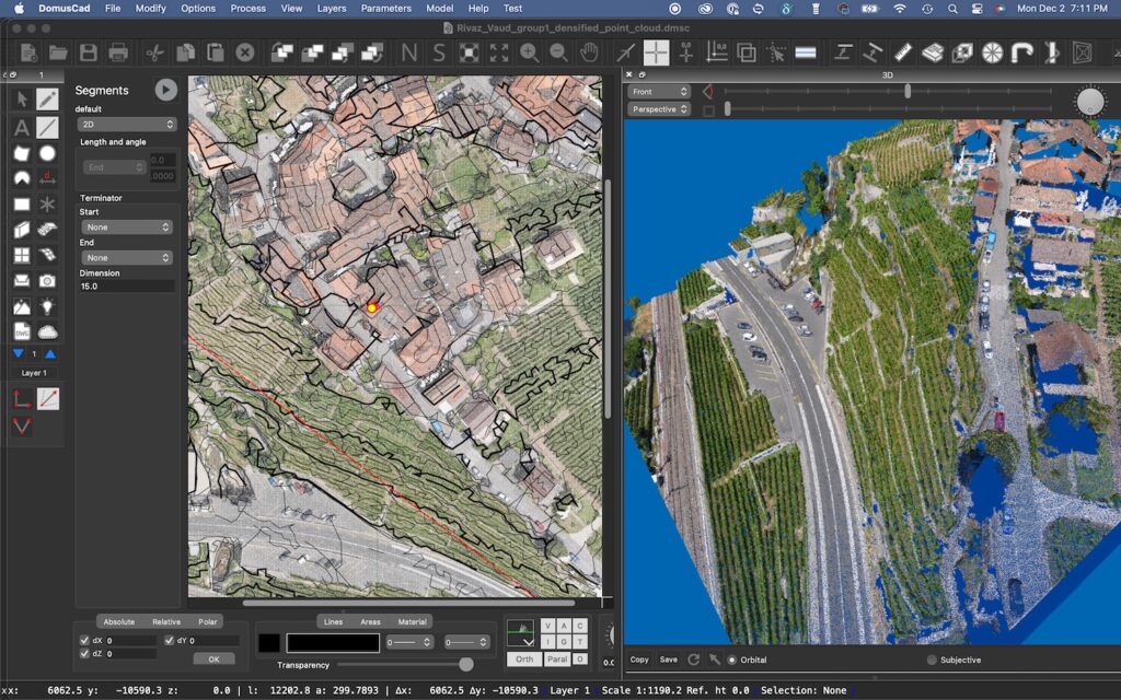
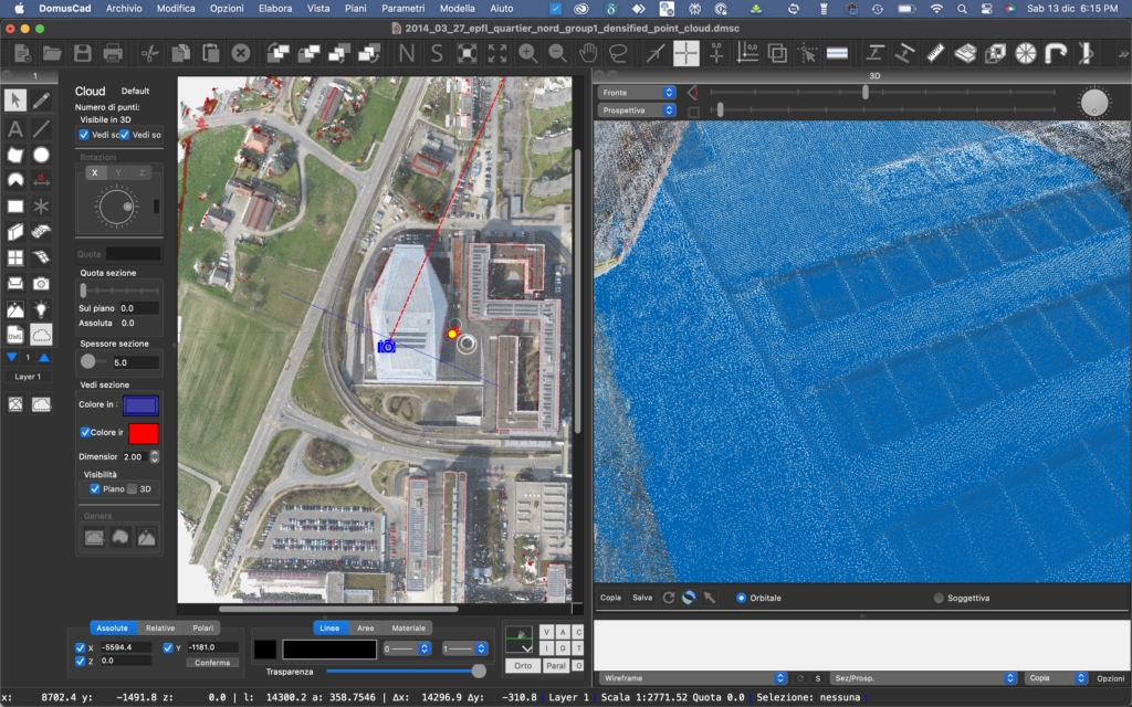
Above a point cloud of an entire hill, detected with a drone. This is a few hundred million points and the representation in the plan on the left with a raster image, exactly referenced and to scale, allows you to work much faster
Movies and tutorials
Here is a series of videos and tutorials that illustrate what is said in this article

Related posts


