 The new version 8 of Geo-Tec B is out with important new functions.
Geo-Tec B allows the verification of stratified slopes in the presence of water beds and loads. Some characteristics are graphic insertion of slope geometry, circular and generic sliding surfaces, stabilization with reinforced zones, pilings and tiebacks, submersed slopes and many others.
See below a detailed descriptions of some of the novelties of the new version 8.
Tiebacks
Tiebacks can be introduced in a slope for stabilizing it.
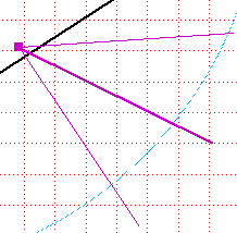
The traction force applied to the tieback is distributed with a diffusion angle that involves the sliding circles and surfaces.
Tiebacks introdution
A tieback is introduced clicking on the icon ![]() , tracing a segment, starting from the anchorage on the terrain profile to a point external to all the sliding surfaces.
, tracing a segment, starting from the anchorage on the terrain profile to a point external to all the sliding surfaces.
The length is the active part of the tieback, excluding the length necessary for anchorage in the terrain strata.
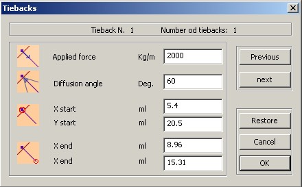
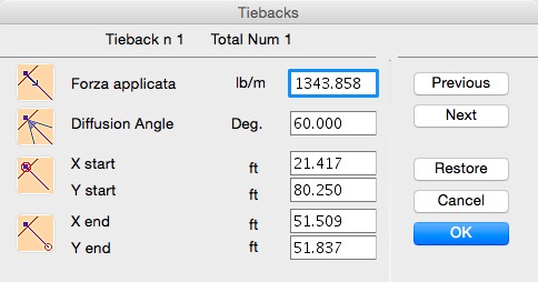
After the mouse button up, a dialog allows the user to numerically change the coordinates and to add the tieback parameters:
X start, Y start, X end and Y end are referred to the start and end extremes of the segment traced with the mouse.
Applied force is the traction force applied to the Tieback.
Diffusion angle. The force applied to a tieback is distributed along the sliding surface with a diffusion angle.
Example:
Tiebacks modification
- Tiebacks can be moved end modified with the mouse dragging the extremes.
- Tiebacks can be modified double clicking on them
- Tiebacks can be modified selecting them and choosing Modify from the Edit/Modify menu.
- Tiebck can be deleted with the Delete Tieback command form the Edit/Modify menu.
Tieback calculation
The force applied to a tieback is distributed along the sliding surface with a diffusion angle.
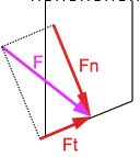
For every slice the force is de-composed in 2 component: tangent and perpendicular to the sliding surface.
F: force applied to the slice
Ft: tangent component along the sliding surface
Fn: perpendicular (normal) component
Ft is directly added to the stabilizing forces.
The contribute of Fn to the stability depends on the friction angle
The contribute to the stability of every slices inside the influence angle of the tieback is:
Ft + Fn tan(Ø)
Where Ø is the friction angle of the stratum.
The calculation of the slope stability with tieback can be done with any method, but is better to use the Janbu method because it considers the horizontal forces between the slices and display the forces diagram.
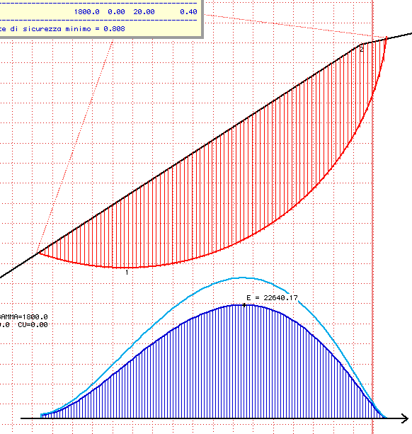
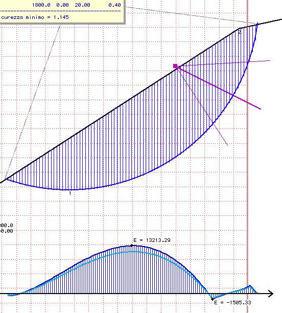
The left picture shows the slop and the forces diagram of the circular sliding surfaces without tiebacks and the right picture shows the same slope after inserting a tieback. It is evident that in the part of the slope with the tieback the forces between the slices are lower.
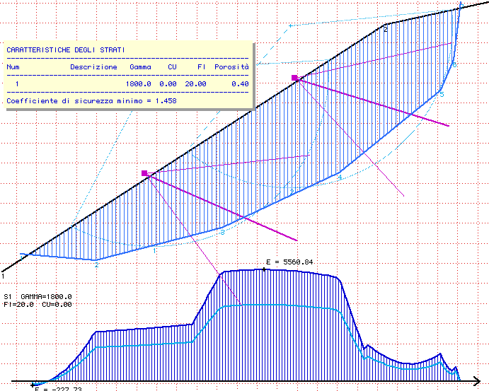
The diagram for a generic sliding surface with 2 tiebacks follows below:
Graphic Interface
A new palette in the top of the working window sustitutes several little icons on the bottom and right sides
From left to right:
- New document
- Open document
- Save
- Copy
- Cut
- Paste
- Zoom Sheet view
- Zoom Natural view
- Zoom –
- Zoom +
- Select zoom
- Redraw
- Evaluate external water
- View stratigraphy
- Recalculate
- Fellenius
- Janbu
- Bishop
- Colors
- Strata fills
- Help
The F and J icons in the activate and visualize the method of calculation used: Fellenius or Janbu. Clicking either of these icons is equal in function to choosing the appropriate command from the Draw menu.
The View and Zoom icons are analogous to choosing the appropriate command from the View menu.
Colors management
Colors can be assigned to text and patterns.
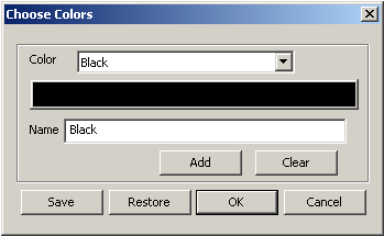
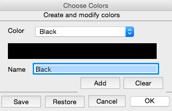
Colors can be created and modified with Draw->Choose colors command.
Mac Os X Windows XP
Clicking the color name recalls a pop-up menu displaying the color list.
Clicking the color block allows the colors to be modified.
A name is associated to each color.
Add : to add a new color. The new color is created with the name “New” and assigned the color Black, and pen number 1.
ATTENTION – If the maximum number of colors have already been used the option is inactive.
Clear: deletes the selected color.
ATTENTION – The first 7 colors cannot be deleted, only changed.
Save: saves the present choice of colors as default parameters for the next time the program is launched.
Restore: restores the values currently present on the hard disk as default.
OK : quits the dialog box and confirms any modifications made.
Cancel : quits the dialog box without confirming the modifications made. Values remain as they were
Assign and modify elements color
![]() The Color icon, form the top palette, set the current color for text and patterns or applies the color designated to the selected profile or traced polygon and to the selected text.
The Color icon, form the top palette, set the current color for text and patterns or applies the color designated to the selected profile or traced polygon and to the selected text.
Others
Working sheet scale
The scale in the Drawing Parameters dialog con be easier and faster chosen with a pop-up menu.
Snap to grid module
The Snap to grid module sub menu changes depending on the current length unit of measure.
Meters
More information on Geo-Tec B
Download a demo version of Geo-Tec B for Windows
Download a trial version of Geo-Tec B for Mac Os


